Ahoy!
Its been quite some time since I set out to complete part two of my home lab write up. Naturally, a lot has changed!!
Physical changes
In part one I discussed by physical layer, this is changed slightly with the addition of my FTTH connection and deprecation of the old crappy FritzBox and related ADSL hardware.
Along with the FTTH connection I switched to using a Juniper SRX210 for CPE after having issues with the Ubiquiti ERL’s and DHCPv6-PD. These days I am up and running with native dual stack thanks to Internode.
I also persisted for a while to use the Rocket M2’s for the PPPoE backhaul before giving in and running cable to make the most of my 100/40 connection. The 2.4Ghz link could only manage ~110Mbps simplex and I configured QOS to ensure only 35Mbps was used in upload. In practice while the radio link was fast enough I was too purist to keep it.
Here is how it looks earlier this year;
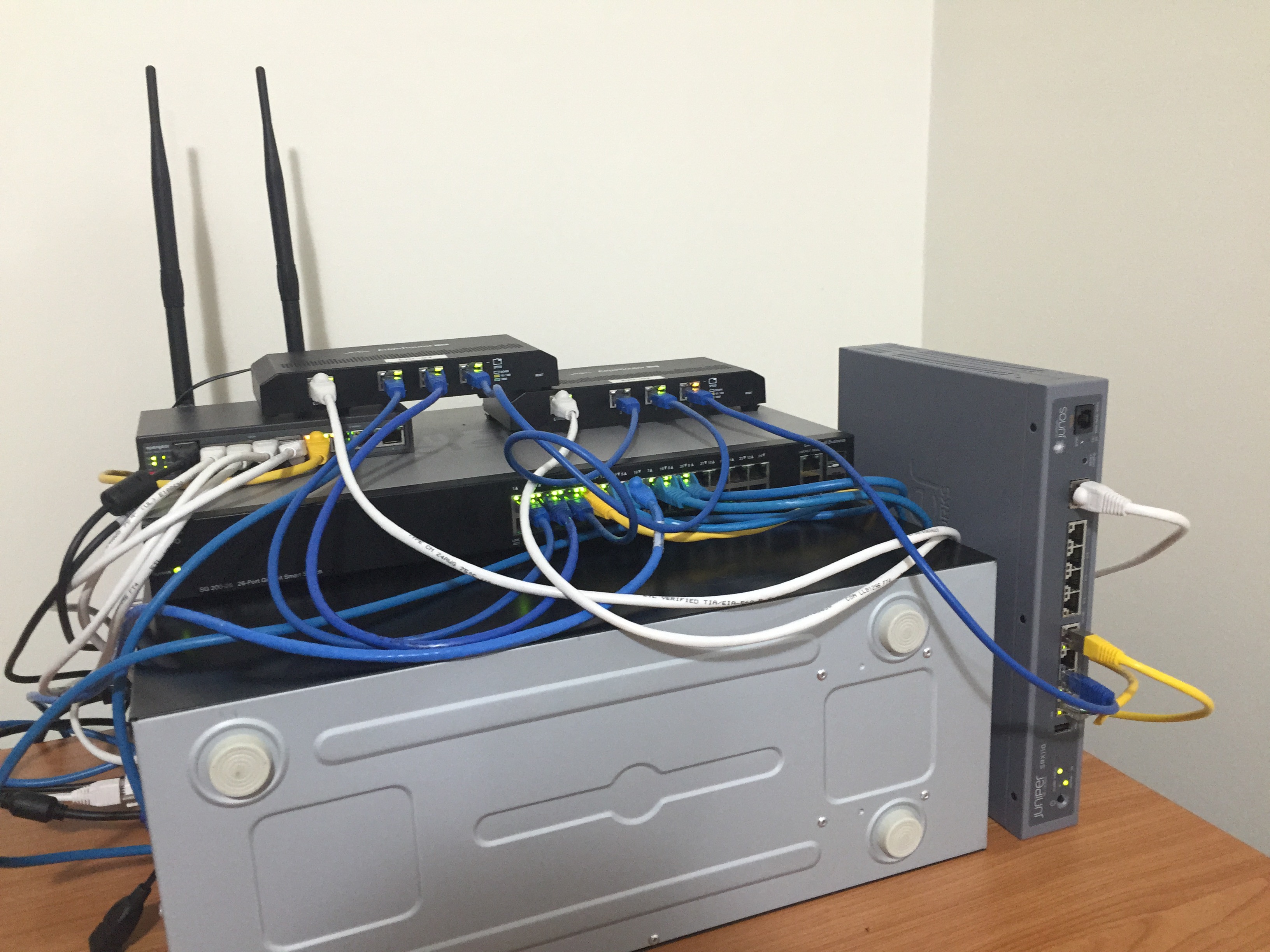
You will see the most exciting addition for me was to lash out and replace the Dovado GO with an Opengear ACM5504-5-LR-I. A huge thanks for the guys at Opengear for all the work they have put into their eco-system and their products. When I deploy one of these boxes it does everything I can possibly ask of it. Want to use PCRE to parse incomming SMS? They have done that. Triggers on environmental alarms? Done that. Automatically multi-homed failover? Tick. SSH to a serial port shell? Yup! Great work guys, please keep it up! (Plus we all know what kind of franken raspi + 4x USB serial adaptors would have been like). If anyone is interested in a more detailed write up on how I am using the ACM5504 please feel free to comment with your questions.
The Network
As promised I have some old diagrams which captured the layer 1 and a hybrid layer 2 / layer 3 diagram. At the moment I have not done a complete layer 3 only routing diagram since I am busily changing things with my DN42 infrastructure. You will get a pretty good idea of my internal OSPF network as well as the different segments and routes anyway.
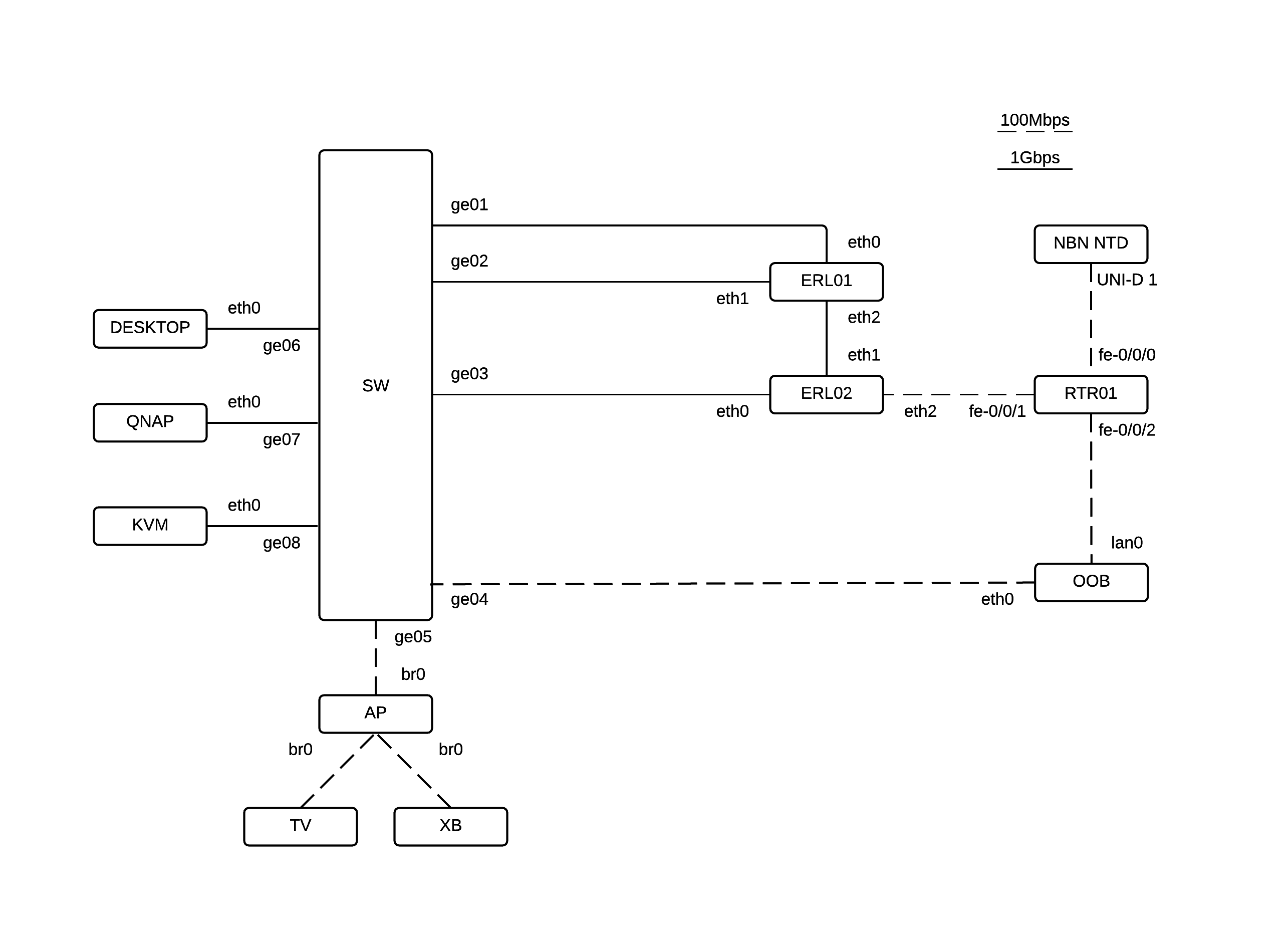
Layer 1
Nothing unexpected here, astute readers will note I stopped using LACP LAG’s and moved back to single gigabit links. The reasoning behind this change was that the Ubiquiti ERL’s cannot use hardware offloading on GNU\Linux bonded interfaces. So in reality your able to get better VLAN routing and throughput on a single link than a bonded one. That being said if you want redundancy at L1 then go ahead and take the hit.
Layer 2 / 3
Here is the really fun part. To decipher the diagram I used a basic key;
- Ovals are subnets
- Recetangles are physical routers
- Circles are destination networks
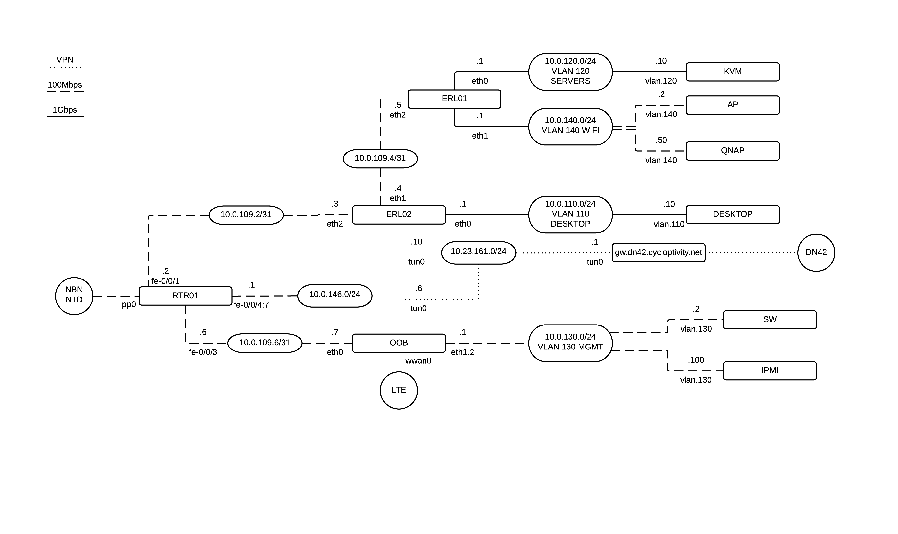
As you can see in this design its a fairly crude campus style L3 design. RTR01 acts the the core while there are two distinct physical networks. The Out Of Band (OOB) network and the campus network.
The campus network is actually the wrong way around and the diagram is incorrectly showing a 100Mbps link between the two ERL’s. The reason for this is simply because of the 3 port count on a ERL. To get 1Gbps to the servers from both guest / wifi and the desktop network it meant using 4 wired ports. Obviously that means a transit link needed to exist between the two. As it turns out this was a fun OSPF implementation anyway.
That is all I have time for now but I hope this can inspire you to pursue your own lab environment. If you have any questions please feel free to use the comments or hit me up online.